Ich habe hier schon einmal über den Bau eines zweiachsigen Solartrackers geschrieben, der auf dem Guss-Schatten-Prinzip basiert. Dann schrieb ich hier über das Testen auf Software-Ebene. Ich habe auch hier und hier darüber geschrieben, wie man es zur Versorgung eines lernbasierten Echtzeitsystems verwendet.
Heute werde ich Ihnen eine Methode vorstellen, mit der wir unseren Solar-Tracker auch auf der Hardware-Ebene getestet haben.
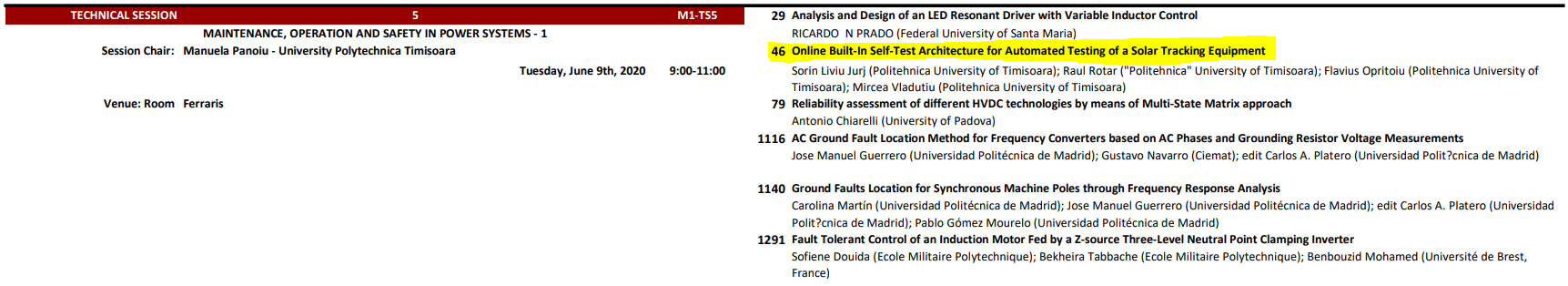
Wir werden morgen das Forschungspapier über diese Eingebaute Online-Selbsttest-Architektur für den automatisierten Test einer Solar-Nachführungsanlage auf der internationalen IEEE-Konferenz 2020 über Umwelt und Elektrotechnik in Madrid, Spanien, vorstellen unter „MAINTENANCE, OPERATION AND SAFETY IN POWER SYSTEMS – 1“.
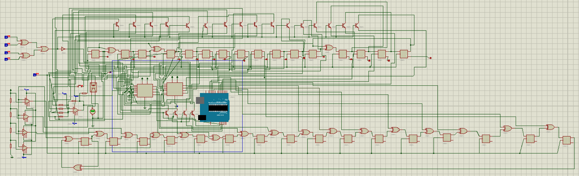
 Zusammenfassung: Dieses Papier stellt eine OBIST-Architektur (Online Built-In Self-Test) vor, die auf die Erkennung von Hardware-Fehlern in Solar-Nachführsystemen zugeschnitten ist. Das Ziel des vorgeschlagenen OBIST ist ein zweifaches: Erstens identifizieren wir die Leerlaufzustände der elektrischen Ausrüstung, die die Nutzlast eines zweiachsigen Solar-Tracker auf die maximale Sonneneinstrahlung ausrichtet, mit Hilfe eines Leerlaufdetektors, der einen minimalen Hardwareaufwand erfordert; zweitens, wenn sich die Solar-Nachführvorrichtung im Leerlaufzustand befindet, trennen wir ihre zu testenden Schaltkreise (CUTs), die aus einem Optokoppler, einem Arduino UNO und zwei L298N-Motortreibern bestehen, vom Hauptdatenstrom (ursprünglich direkt mit dem Solarpanel verbunden) und schließen die vorgeschlagene OBIST-Ausrüstung über spezielle Schalter an, um Testvektoren einzuspeisen und ihre Ausgangssignale in einer signaturbasierten Reaktionsweise zu sammeln. Die auf unserer Hardware-Implementierung und Softwaresimulation basierenden Versuchsergebnisse erreichen eine durchschnittliche Abdeckung von 93,93% für einzelne Bit-Flip-Fehler (letzte 8 Bits, mutiert), 100% für einzelne „stuck-at-faults“ (8, 12 und 16 zufällige Bits) sowie 96,96% für alle Zielfehler, was zeigt, dass die vorgeschlagene OBIST-Architektur hinsichtlich der Testabdeckung und der Kosten effizient ist.
 Sie können den Artikel hier lesen.
Hier habe ich alle Projektdateien bezüglich unserer Eingebaute Online-Selbsttest-Architektur für den automatisierten Test einer Solar-Nachführungsanlage veröffentlicht.

OBIST Fault Coverage C Code
/* Author: Sorin Liviu Jurj.
* This code is written for our paper called Online Built-In Self-Test Architecture for Automated Testing of a Solar Tracking Equipment.
* More info about this project can be found here: https://www.jurj.de/online-built-in-self-test-architecture-for-automated-testing-of-a-solar-tracking-equipment
*/
#include <stdio.h>
#include <stdlib.h>
#include <inttypes.h>
uint8_t* LFSR (uint8_t *in);
uint8_t* CUT_Golden (uint8_t *in, uint8_t EnA, uint8_t EnB);
uint8_t* CUT_Faulty_S (uint8_t *in, uint8_t EnA, uint8_t EnB);
uint8_t* CUT_Faulty_D (uint8_t *in, uint8_t EnA, uint8_t EnB);
uint8_t* CUT_Faulty_ST (uint8_t *in, uint8_t EnA, uint8_t EnB);
uint8_t* MISR (uint8_t *in, uint8_t* out);
int main()
{
uint8_t Q[16] = {1, 1, 1, 1, 1, 1, 1, 1, 1 ,1 ,1 , 1, 1, 1, 1, 1}, // LFSR Register with initial value
*ptr1, *ptr2, *ptr3, *ptr4,
M[16] = {0, 1, 0, 0, 0, 0, 1, 1, 0 ,0 ,0 , 0, 0, 0, 0, 0}; // MISR Register with initial value
unsigned int i, j;
float count1, count2, count3, count4, count5;
printf(“ LFSR\t MISR_Golden\t MISR_Faulty\n“);
//printf(„Q0 Q1 Q2 Q3 Q4 Q5 Q6 Q7 Q8 Q9 Q10 Q11 Q12 Q13 Q14 Q15\tQ_G0 Q_G1 Q_G2 Q_G3 Q_G4 Q_G5 Q_G6 Q_G7 Q_G8 Q_G9 Q_G10 Q_G11 Q_G12 Q_G13 Q_G14 Q_G15tQ_F0 Q_F1 Q_F2 Q_F3 Q_F4 Q_F5 Q_F6 Q_F7 Q_F8 Q_F9 Q_F10 Q_F11 Q_F12 Q_F13 Q_F14 Q_F15t\n“);
for(i = 0 ; i<65535; i++)
{
ptr1 = MISR(M,CUT_Golden(LFSR(Q), 1 , 1));
ptr2 = MISR(M,CUT_Faulty_S(LFSR(Q), 1 , 1));
ptr3 = MISR(M,CUT_Faulty_ST(LFSR(Q), 1 , 1));
ptr4 = MISR(M,CUT_Faulty_D(LFSR(Q), 1 , 1));
// printf(„%2d %2d %2d %2d %2d %2d %2d %2d %2d %2d %2d %2d %2d %2d %2d %2d\t“, Q[0], Q[1], Q[2], Q[3], Q[4], Q[5], Q[6], Q[7], Q[8], Q[9], Q[10], Q[11], Q[12], Q[13], Q[14], Q[15]);
// printf(„%2d %2d %2d %2d %2d %2d %2d %2d %2d %2d %2d %2d %2d %2d %2d %2d\t“, ptr1[0], ptr1[1], ptr1[2], ptr1[3], ptr1[4], ptr1[5], ptr1[6], ptr1[7], ptr1[8], ptr1[9], ptr1[10], ptr1[11], ptr1[12], ptr1[13], ptr1[14], ptr1[15]);
// printf(„%2d %2d %2d %2d %2d %2d %2d %2d %2d %2d %2d %2d %2d %2d %2d %2d\n“, ptr2[0], ptr2[1], ptr2[2], ptr2[3], ptr2[4], ptr2[5], ptr2[6], ptr2[7], ptr2[8], ptr2[9], ptr2[10], ptr2[11], ptr2[12], ptr2[13], ptr2[14], ptr2[15]);
if(ptr1[0] == ptr2[0] && ptr1[1] == ptr2[1] && ptr1[2] == ptr2[2] && ptr1[3] == ptr2[3] && ptr1[4] == ptr2[4] && ptr1[5] == ptr2[5]&& ptr1[6] == ptr2[6] && ptr1[7] == ptr2[7] && ptr1[8] == ptr2[8] && ptr1[9] == ptr2[9] && ptr1[10] == ptr2[10] && ptr1[11] == ptr2[11]&& ptr1[12] == ptr2[12] && ptr1[13] == ptr2[13] && ptr1[14] == ptr2[14] && ptr1[15] == ptr2[15]){
count1++;
}
if(ptr1[0] == ptr3[0] && ptr1[1] == ptr3[1] && ptr1[2] == ptr3[2] && ptr1[3] == ptr3[3] && ptr1[4] == ptr3[4] && ptr1[5] == ptr3[5]&& ptr1[6] == ptr3[6] && ptr1[7] == ptr3[7] && ptr1[8] == ptr3[8] && ptr1[9] == ptr3[9] && ptr1[10] == ptr3[10] && ptr1[11] == ptr3[11]&& ptr1[12] == ptr3[12] && ptr1[13] == ptr3[13] && ptr1[14] == ptr3[14] && ptr1[15] == ptr3[15]){
count2++;
}
for( j = 0; j < 16; j++ ) {
if( 1 == ( ptr1[j] & 1 ) ) {
count3++;
}
if( 1 == ( ptr4[j] & 1 ) ) {
count4++;
}
}
if(count3 == count4){
// Double parity detected.
count5++;
}
}
printf(„*******The software implementation of BILBO evaluates the fault coverage for different fault models.********\n\n“);
printf(„The fault coverage is single bit fault is %f and %f.\n“, count1, count1/65535);
printf(„The fault coverage is single double fault is %f and %f.\n“, count2, count2/65535);
printf(„The fault coverage is single stuck-at fault is %f and %f.\n“, count5, count5/65535);
return 0;
}
/* LFSR Logical Module of LFSR takes in the present value and return the next value
* Input in – present value of LFSR Q0, Q1, Q2, Q3 ……..Q15.
* Returns the next vector
* Implementing the polynomial 1+x+x^3+x^12+x^16
*/
uint8_t* LFSR (uint8_t *in)
{
uint8_t tmp = in[15]; // store Q[16] because it’ll change in next line
in[15] = in[14];
in[14] = in[13];
in[13] = in[12];
in[12] = in[11] ^ tmp;
in[11] = in[10];
in[10] = in[9];
in[9] = in[8];
in[8] = in[7];
in[7] = in[6];
in[6] = in[5];
in[5] = in[4];
in[4] = in[3];
in[3] = in[2] ^ tmp; // Q[3] <- Q[2] shift to right
in[2] = in[1]; // Q[2] <- Q[1] shift to right
in[1] = in[0] ^ tmp; // Q[1] <- Q[0] ^ Q[3] shift to right EXOR feedback loop
in[0] = tmp; // Q[0] <- Q[3] shift to right
return in;
}
//*************** This is the description of the Golden DUT****************************
/* CUT circuit under test Logical module of the CUT
* CUT contains 1 optocoupler, 2 L298 motor drivers and one arduino uno microcontroller.
* Input in – value of 4 pin IN1, IN2, IN3, IN4
* EnA, EnB – value of Enable pins High or Low
* returns value of the output of L298N as an array of OUT1, OUT2, OUT3, OUT4
*/
uint8_t* CUT_Golden (uint8_t *in, uint8_t EnA, uint8_t EnB)
{
uint8_t analogue;
static uint8_t out[15]; // Output of L298N depends on input line directly and Enable Line
//* First we will model the optocoupler as we know that it will use DAC and ADC
//* Now we are implementing the bit DAC
if (in[0] == 0 && in[1] == 0 && in[2] == 0 && in[3] == 0){
analogue = 0.1;
}
if (in[0] == 0 && in[1] == 0 && in[2] == 0 && in[3] == 1){
analogue = 0.3;
}
if (in[0] == 0 && in[1] == 0 && in[2] == 1 && in[3] == 0){
analogue = 0.6;
}
if (in[0] == 0 && in[1] == 0 && in[2] == 1 && in[3] == 1){
analogue = 0.9;
}
if (in[0] == 0 && in[1] == 1 && in[2] == 0 && in[3] == 0){
analogue = 1.2;
}
if (in[0] == 0 && in[1] == 1 && in[2] == 0 && in[3] == 1){
analogue = 1.5;
}
if (in[0] == 0 && in[1] == 1 && in[2] == 1 && in[3] == 0){
analogue = 1.8;
}
if (in[0] == 0 && in[1] == 1 && in[2] == 1 && in[3] == 1){
analogue = 2.1;
}
if (in[0] == 1 && in[1] == 0 && in[2] == 0 && in[3] == 0){
analogue = 2.4;
}
if (in[0] == 1 && in[1] == 0 && in[2] == 0 && in[3] == 1){
analogue = 2.7;
}
if (in[0] == 1 && in[1] == 0 && in[2] == 1 && in[3] == 0){
analogue = 3.0;
}
if (in[0] == 1 && in[1] == 0 && in[2] == 1 && in[3] == 1){
analogue = 3.3;
}
if (in[0] == 1 && in[1] == 1 && in[2] == 0 && in[3] == 0){
analogue = 3.6;
}
if (in[0] == 1 && in[1] == 1 && in[2] == 0 && in[3] == 1){
analogue = 3.9;
}
if (in[0] == 1 && in[1] == 1 && in[2] == 1 && in[3] == 0){
analogue = 4.2;
}
if (in[0] == 1 && in[1] == 1 && in[2] == 1 && in[3] == 1){
analogue = 4.5;
}
//% we have finished the implementation of the DAC, now we will implement the optocoupler and analogue to digital ADC.
if (analogue > 0.7){
if (analogue == 0.9){
out[0] = 0;
out[1] = 1;
out[2] = 0;
out[3] = 0;
}
if (analogue == 1.2){
out[0] = 0;
out[1] = 1;
out[2] = 0;
out[3] = 1;
}
if (analogue == 1.5){
out[0] = 0;
out[1] = 1;
out[2] = 1;
out[3] = 0;
}
if (analogue == 1.8){
out[0] = 0;
out[1] = 1;
out[2] = 1;
out[3] = 1;
}
if (analogue == 2.1){
out[0] = 1;
out[1] = 0;
out[2] = 0;
out[3] = 0;
}
if (analogue == 2.4){
out[0] = 1;
out[1] = 0;
out[2] = 0;
out[3] = 1;
}
if (analogue == 2.7){
out[0] = 1;
out[1] = 0;
out[2] = 1;
out[3] = 0;
}
if (analogue == 3.0){
out[0] = 1;
out[1] = 0;
out[2] = 1;
out[3] = 1;
}
if (analogue == 3.3){
out[0] = 1;
out[1] = 1;
out[2] = 0;
out[3] = 0;
}
if (analogue == 3.6){
out[0] = 1;
out[1] = 1;
out[2] = 0;
out[3] = 1;
}
if (analogue == 3.9){
out[0] = 1;
out[1] = 1;
out[2] = 1;
out[3] = 0;
}
if (analogue == 4.2){
out[0] = 1;
out[1] = 1;
out[2] = 1;
out[3] = 1;
}
}
/* We have implemented the first part of the CUT, now we will implement the second part
* The second part consists of L298 motor driver.
*/
out[4] = in[4] && EnA; // OUT1 = IN1.EnA
out[5] = in[5] && EnA; // OUT2 = IN2.EnA
out[6] = in[6] && EnB; // OUT3 = IN3.EnB
out[7] = in[7] && EnB; // OUT4 = IN4.EnB
/* We have implemented the second part of the CUT, now we will implement the third part
* The third part also consists of L298 motor driver.
*/
out[8] = in[8] && EnA; // OUT1 = IN1.EnA
out[9] = in[9] && EnA; // OUT2 = IN2.EnA
out[10] = in[10] && EnB; // OUT3 = IN3.EnB
out[11] = in[11] && EnB; // OUT4 = IN4.EnB
/*
* The last part of the CUT is Arduino Uno and the circuit of the arduino depends upon the program that is loaded in
* the micro-controller. Consider that the code implements 4 XOR gates in Arduino Uno.
*/
out[12] = in[12] ^ in[13]; // OUT1 = IN1.EnA
out[13] = in[13] ^ in[14]; // OUT2 = IN2.EnA
out[14] = in[14] ^ in[15]; // OUT3 = IN3.EnB
out[15] = in[15] ^ in[12]; // OUT4 = IN4.EnB
return out;
}
//*************** This is the description of the Faulty DUT (Single bit fault)****************************
/* CUT circuit under test Logical module of the CUT
* CUT contains 1 optocoupler, 2x L298 motor drivers and one arduino uno microcontroller.
* Input in – value of 4 pin IN1, IN2, IN3, IN4
* EnA, EnB – value of Enable pins High or Low
* returns value of the output of L298N as an array of OUT1, OUT2, OUT3, OUT4
*/
uint8_t* CUT_Faulty_S (uint8_t *in, uint8_t EnA, uint8_t EnB)
{
uint8_t analogue;
static uint8_t out[15]; // Output of L298N depends on input line directly and Enable Line
//* First we will model the opto-coupler as we know that it will use DAC and ADC
//* Now we are implementing the bit DAC
if (in[0] == 0 && in[1] == 0 && in[2] == 0 && in[3] == 0){
analogue = 0.1;
}
if (in[0] == 0 && in[1] == 0 && in[2] == 0 && in[3] == 1){
analogue = 0.3;
}
if (in[0] == 0 && in[1] == 0 && in[2] == 1 && in[3] == 0){
analogue = 0.6;
}
if (in[0] == 0 && in[1] == 0 && in[2] == 1 && in[3] == 1){
analogue = 0.9;
}
if (in[0] == 0 && in[1] == 1 && in[2] == 0 && in[3] == 0){
analogue = 1.2;
}
if (in[0] == 0 && in[1] == 1 && in[2] == 0 && in[3] == 1){
analogue = 1.5;
}
if (in[0] == 0 && in[1] == 1 && in[2] == 1 && in[3] == 0){
analogue = 1.8;
}
if (in[0] == 0 && in[1] == 1 && in[2] == 1 && in[3] == 1){
analogue = 2.1;
}
if (in[0] == 1 && in[1] == 0 && in[2] == 0 && in[3] == 0){
analogue = 2.4;
}
if (in[0] == 1 && in[1] == 0 && in[2] == 0 && in[3] == 1){
analogue = 2.7;
}
if (in[0] == 1 && in[1] == 0 && in[2] == 1 && in[3] == 0){
analogue = 3.0;
}
if (in[0] == 1 && in[1] == 0 && in[2] == 1 && in[3] == 1){
analogue = 3.3;
}
if (in[0] == 1 && in[1] == 1 && in[2] == 0 && in[3] == 0){
analogue = 3.6;
}
if (in[0] == 1 && in[1] == 1 && in[2] == 0 && in[3] == 1){
analogue = 3.9;
}
if (in[0] == 1 && in[1] == 1 && in[2] == 1 && in[3] == 0){
analogue = 4.2;
}
if (in[0] == 1 && in[1] == 1 && in[2] == 1 && in[3] == 1){
analogue = 4.5;
}
//% we have finished the implementation of the DAC, now we will implement the optocoupler and analogue to digital ADC.
if (analogue > 0.7){
if (analogue == 0.9){
out[0] = 0;
out[1] = 1;
out[2] = 0;
out[3] = 0;
}
if (analogue == 1.2){
out[0] = 0;
out[1] = 1;
out[2] = 0;
out[3] = 1;
}
if (analogue == 1.5){
out[0] = 0;
out[1] = 1;
out[2] = 1;
out[3] = 0;
}
if (analogue == 1.8){
out[0] = 0;
out[1] = 1;
out[2] = 1;
out[3] = 1;
}
if (analogue == 2.1){
out[0] = 1;
out[1] = 0;
out[2] = 0;
out[3] = 0;
}
if (analogue == 2.4){
out[0] = 1;
out[1] = 0;
out[2] = 0;
out[3] = 1;
}
if (analogue == 2.7){
out[0] = 1;
out[1] = 0;
out[2] = 1;
out[3] = 0;
}
if (analogue == 3.0){
out[0] = 1;
out[1] = 0;
out[2] = 1;
out[3] = 1;
}
if (analogue == 3.3){
out[0] = 1;
out[1] = 1;
out[2] = 0;
out[3] = 0;
}
if (analogue == 3.6){
out[0] = 1;
out[1] = 1;
out[2] = 0;
out[3] = 1;
}
if (analogue == 3.9){
out[0] = 1;
out[1] = 1;
out[2] = 1;
out[3] = 0;
}
if (analogue == 4.2){
out[0] = 1;
out[1] = 1;
out[2] = 1;
out[3] = 1;
}
}
/* We have implemented the first part of the CUT, now we will implement the second part
* The second part consists of L298 motor driver.
*/
out[4] = in[4] ^ EnA; // OUT1 = IN1.EnA Note: we place one mutant in motor driver circuit. (Replaced && by ^).
out[5] = in[5] && EnA; // OUT2 = IN2.EnA
out[6] = in[6] && EnB; // OUT3 = IN3.EnB
out[7] = in[7] && EnB; // OUT4 = IN4.EnB
/* We have implemented the second part of the CUT, now we will implement the third part
* The third part also consists of L298 motor driver.
*/
out[8] = in[8] && EnA; // OUT1 = IN1.EnA
out[9] = in[9] && EnA; // OUT2 = IN2.EnA
out[10] = in[10] && EnB; // OUT3 = IN3.EnB
out[11] = in[11] && EnB; // OUT4 = IN4.EnB
/*
* The last part of the CUT is Arduino Uno and the circuit of the arduino depends upon the program that is loaded in
* the micro-controller. Consider that the code implements 4 XOR gates in Arduino Uno.
*/
out[12] = in[12] ^ in[13]; // OUT1 = IN1.EnA
out[13] = in[13] ^ in[14]; // OUT2 = IN2.EnA
out[14] = in[14] ^ in[15]; // OUT3 = IN3.EnB
out[15] = in[15] ^ in[12]; // OUT4 = IN4.EnB
return out;
}
//*************** This is the description of the Faulty DUT (Double bit fault)****************************
/* CUT circuit under test Logical module of the CUT
* CUT contains 1 optocoupler, 2x L298 motor drivers and one arduino uno microcontroller.
* Input in – value of 4 pin IN1, IN2, IN3, IN4
* EnA, EnB – value of Enable pins High or Low
* returns value of the output of L298N as an array of OUT1, OUT2, OUT3, OUT4
*/
uint8_t* CUT_Faulty_D (uint8_t *in, uint8_t EnA, uint8_t EnB)
{
uint8_t analogue;
static uint8_t out[15]; // Output of L298N depends on input line directly and Enable Line
//* First we will model the optocoupler as we know that it will use DAC and ADC
//* Now we are implementing the bit DAC
if (in[0] == 0 && in[1] == 0 && in[2] == 0 && in[3] == 0){
analogue = 0.1;
}
if (in[0] == 0 && in[1] == 0 && in[2] == 0 && in[3] == 1){
analogue = 0.3;
}
if (in[0] == 0 && in[1] == 0 && in[2] == 1 && in[3] == 0){
analogue = 0.6;
}
if (in[0] == 0 && in[1] == 0 && in[2] == 1 && in[3] == 1){
analogue = 0.9;
}
if (in[0] == 0 && in[1] == 1 && in[2] == 0 && in[3] == 0){
analogue = 1.2;
}
if (in[0] == 0 && in[1] == 1 && in[2] == 0 && in[3] == 1){
analogue = 1.5;
}
if (in[0] == 0 && in[1] == 1 && in[2] == 1 && in[3] == 0){
analogue = 1.8;
}
if (in[0] == 0 && in[1] == 1 && in[2] == 1 && in[3] == 1){
analogue = 2.1;
}
if (in[0] == 1 && in[1] == 0 && in[2] == 0 && in[3] == 0){
analogue = 2.4;
}
if (in[0] == 1 && in[1] == 0 && in[2] == 0 && in[3] == 1){
analogue = 2.7;
}
if (in[0] == 1 && in[1] == 0 && in[2] == 1 && in[3] == 0){
analogue = 3.0;
}
if (in[0] == 1 && in[1] == 0 && in[2] == 1 && in[3] == 1){
analogue = 3.3;
}
if (in[0] == 1 && in[1] == 1 && in[2] == 0 && in[3] == 0){
analogue = 3.6;
}
if (in[0] == 1 && in[1] == 1 && in[2] == 0 && in[3] == 1){
analogue = 3.9;
}
if (in[0] == 1 && in[1] == 1 && in[2] == 1 && in[3] == 0){
analogue = 4.2;
}
if (in[0] == 1 && in[1] == 1 && in[2] == 1 && in[3] == 1){
analogue = 4.5;
}
//% we have finished the implementation of the DAC, now we will implement the optocoupler and analogue to digital ADC.
if (analogue > 0.7){
if (analogue == 0.9){
out[0] = 0;
out[1] = 1;
out[2] = 0;
out[3] = 0;
}
if (analogue == 1.2){
out[0] = 0;
out[1] = 1;
out[2] = 0;
out[3] = 1;
}
if (analogue == 1.5){
out[0] = 0;
out[1] = 1;
out[2] = 1;
out[3] = 0;
}
if (analogue == 1.8){
out[0] = 0;
out[1] = 1;
out[2] = 1;
out[3] = 1;
}
if (analogue == 2.1){
out[0] = 1;
out[1] = 0;
out[2] = 0;
out[3] = 0;
}
if (analogue == 2.4){
out[0] = 1;
out[1] = 0;
out[2] = 0;
out[3] = 1;
}
if (analogue == 2.7){
out[0] = 1;
out[1] = 0;
out[2] = 1;
out[3] = 0;
}
if (analogue == 3.0){
out[0] = 1;
out[1] = 0;
out[2] = 1;
out[3] = 1;
}
if (analogue == 3.3){
out[0] = 1;
out[1] = 1;
out[2] = 0;
out[3] = 0;
}
if (analogue == 3.6){
out[0] = 1;
out[1] = 1;
out[2] = 0;
out[3] = 1;
}
if (analogue == 3.9){
out[0] = 1;
out[1] = 1;
out[2] = 1;
out[3] = 0;
}
if (analogue == 4.2){
out[0] = 1;
out[1] = 1;
out[2] = 1;
out[3] = 1;
}
}
/* We have implemented the first part of the CUT, now we will implement the second part
* The second part consists of L298 motor driver.
*/
out[4] = in[4] ^ EnA; // OUT1 = IN1.EnA Note: we place one mutant in motor driver circuit. (Replaced && by ^).
out[5] = in[5] && EnA; // OUT2 = IN2.EnA
out[6] = in[6] && EnB; // OUT3 = IN3.EnB
out[7] = in[7] && EnB; // OUT4 = IN4.EnB
/* We have implemented the second part of the CUT, now we will implement the third part
* The third part also consists of L298 motor driver.
*/
out[8] = in[8] ^ EnA; // OUT1 = IN1.EnA Note: we place one mutant in motor driver circuit. (Replaced && by ^).
out[9] = in[9] && EnA; // OUT2 = IN2.EnA
out[10] = in[10] && EnB; // OUT3 = IN3.EnB
out[11] = in[11] && EnB; // OUT4 = IN4.EnB
/*
* The last part of the CUT is Arduino Uno and the circuit of the arduino depends upon the program that is loaded in
* the micro-controller. Consider that the code implements 4 XOR gates in Arduino Uno.
*/
out[12] = in[12] ^ in[13]; // OUT1 = IN1.EnA
out[13] = in[13] ^ in[14]; // OUT2 = IN2.EnA
out[14] = in[14] ^ in[15]; // OUT3 = IN3.EnB
out[15] = in[15] ^ in[12]; // OUT4 = IN4.EnB
return out;
}
uint8_t* CUT_Faulty_ST (uint8_t *in, uint8_t EnA, uint8_t EnB)
{
uint8_t analogue;
static uint8_t out[15]; // Output of L298N depends on input line directly and Enable Line
//* First we will model the optocoupler as we know that it will use DAC and ADC
//* Now we are implementing the bit DAC
if (in[0] == 0 && in[1] == 0 && in[2] == 0 && in[3] == 0){
analogue = 0.1;
}
if (in[0] == 0 && in[1] == 0 && in[2] == 0 && in[3] == 1){
analogue = 0.3;
}
if (in[0] == 0 && in[1] == 0 && in[2] == 1 && in[3] == 0){
analogue = 0.6;
}
if (in[0] == 0 && in[1] == 0 && in[2] == 1 && in[3] == 1){
analogue = 0.9;
}
if (in[0] == 0 && in[1] == 1 && in[2] == 0 && in[3] == 0){
analogue = 1.2;
}
if (in[0] == 0 && in[1] == 1 && in[2] == 0 && in[3] == 1){
analogue = 1.5;
}
if (in[0] == 0 && in[1] == 1 && in[2] == 1 && in[3] == 0){
analogue = 1.8;
}
if (in[0] == 0 && in[1] == 1 && in[2] == 1 && in[3] == 1){
analogue = 2.1;
}
if (in[0] == 1 && in[1] == 0 && in[2] == 0 && in[3] == 0){
analogue = 2.4;
}
if (in[0] == 1 && in[1] == 0 && in[2] == 0 && in[3] == 1){
analogue = 2.7;
}
if (in[0] == 1 && in[1] == 0 && in[2] == 1 && in[3] == 0){
analogue = 3.0;
}
if (in[0] == 1 && in[1] == 0 && in[2] == 1 && in[3] == 1){
analogue = 3.3;
}
if (in[0] == 1 && in[1] == 1 && in[2] == 0 && in[3] == 0){
analogue = 3.6;
}
if (in[0] == 1 && in[1] == 1 && in[2] == 0 && in[3] == 1){
analogue = 3.9;
}
if (in[0] == 1 && in[1] == 1 && in[2] == 1 && in[3] == 0){
analogue = 4.2;
}
if (in[0] == 1 && in[1] == 1 && in[2] == 1 && in[3] == 1){
analogue = 4.5;
}
//% we have finished the implementation of the DAC, now we will implement the optocoupler and analogue to digital ADC.
if (analogue > 0.7){
if (analogue == 0.9){
out[0] = 0;
out[1] = 1;
out[2] = 0;
out[3] = 0;
}
if (analogue == 1.2){
out[0] = 0;
out[1] = 1;
out[2] = 0;
out[3] = 1;
}
if (analogue == 1.5){
out[0] = 0;
out[1] = 1;
out[2] = 1;
out[3] = 0;
}
if (analogue == 1.8){
out[0] = 0;
out[1] = 1;
out[2] = 1;
out[3] = 1;
}
if (analogue == 2.1){
out[0] = 1;
out[1] = 0;
out[2] = 0;
out[3] = 0;
}
if (analogue == 2.4){
out[0] = 1;
out[1] = 0;
out[2] = 0;
out[3] = 1;
}
if (analogue == 2.7){
out[0] = 1;
out[1] = 0;
out[2] = 1;
out[3] = 0;
}
if (analogue == 3.0){
out[0] = 1;
out[1] = 0;
out[2] = 1;
out[3] = 1;
}
if (analogue == 3.3){
out[0] = 1;
out[1] = 1;
out[2] = 0;
out[3] = 0;
}
if (analogue == 3.6){
out[0] = 1;
out[1] = 1;
out[2] = 0;
out[3] = 1;
}
if (analogue == 3.9){
out[0] = 1;
out[1] = 1;
out[2] = 1;
out[3] = 0;
}
if (analogue == 4.2){
out[0] = 1;
out[1] = 1;
out[2] = 1;
out[3] = 1;
}
}
/* We have implemented the first part of the CUT, now we will implement the second part
* The second part consists of L298 motor driver.
*/
out[4] = 1; // OUT1 = IN1.EnA Note: Stuck at fault.
out[5] = in[5] && EnA; // OUT2 = IN2.EnA
out[6] = in[6] && EnB; // OUT3 = IN3.EnB
out[7] = in[7] && EnB; // OUT4 = IN4.EnB
/* We have implemented the second part of the CUT, now we will implement the third part
* The third part also consists of L298 motor driver.
*/
out[8] = in[8] && EnA; // OUT1 = IN1.EnA
out[9] = in[9] && EnA; // OUT2 = IN2.EnA
out[10] = in[10] && EnB; // OUT3 = IN3.EnB
out[11] = in[11] && EnB; // OUT4 = IN4.EnB
/*
* The last part of the CUT is Arduino Uno and the circuit of the arduino depends upon the program that is loaded in
* the microcontroller. Consider that the code implements 4 XOR gates in Arduino Uno.
*/
out[12] = in[12] ^ in[13]; // OUT1 = IN1.EnA
out[13] = in[13] ^ in[14]; // OUT2 = IN2.EnA
out[14] = in[14] ^ in[15]; // OUT3 = IN3.EnB
out[15] = in[15] ^ in[12]; // OUT4 = IN4.EnB
return out;
}
/* MISR Logical module of the MISR
takes the present value and calculate the new based on L298N output
stores it back in MISR register
* Inputs in – values of the MISR register Q0, Q1, Q2, Q3 of MISR
* out – values of L298N output OUT1, OUT2, OUT3, OUT4
* returns new value of the MISR register after processing
*/
uint8_t* MISR (uint8_t *in, uint8_t* out)
{
uint8_t tmp = in[15]; // store Q[3] because it’ll change in next line
in[15] = in[14] ^ out[15]; // Q[3] <- Q[2] ^ OUT4
in[14] = in[13] ^ out[14]; // Q[2] <- Q[1] ^ OUT3
in[13] = in[12] ^ out[13]; // Q[1] <- Q[0] ^ OUT2
in[12] = in[11] ^ out[11]; // Q[0] <- ( Q[0] ^ Q[3] ) ^ OUT1
in[11] = in[10] ^ out[11]; // Q[3] <- Q[2] ^ OUT4
in[10] = in[9] ^ out[10]; // Q[2] <- Q[1] ^ OUT3
in[9] = in[8] ^ out[9]; // Q[1] <- Q[0] ^ OUT2
in[8] = in[7] ^ out[8]; // Q[0] <- ( Q[0] ^ Q[3] ) ^ OUT1
in[7] = in[6] ^ out[7]; // Q[3] <- Q[2] ^ OUT4
in[6] = in[5] ^ out[6]; // Q[2] <- Q[1] ^ OUT3
in[5] = in[4] ^ out[5]; // Q[1] <- Q[0] ^ OUT2
in[4] = in[3] ^ out[4]; // Q[0] <- ( Q[0] ^ Q[3] ) ^ OUT1
in[3] = in[2] ^ out[3]; // Q[3] <- Q[2] ^ OUT4
in[2] = in[1] ^ out[2]; // Q[2] <- Q[1] ^ OUT3
in[1] = in[0] ^ out[1]; // Q[1] <- Q[0] ^ OUT2
in[0] = (in[0] ^ tmp ) ^ out[0]; // Q[0] <- ( Q[0] ^ Q[3] ) ^ OUT1
return in;
}
Questions Regarding the “Online Built-In Self-Test Architecture for Automated Testing of a Solar Tracking Equipment” Article
Q1. What was the motivation behind the implementation of an Online Built-In Self-test Architecture to test solar tracking equipment?
A1. We consider that green energy is vital for our environment and society. Solar panels, as well as solar tracking systems, are becoming more popular in recent years due to reduced production and maintenance costs. We are aware of the fact that security issues can impact the performance of solar tracking devices and reduce energy harvesting. Therefore our objective is to implement a low cost and efficient OBIST architecture that can detect hardware errors in real-time to obtain high fault coverage for all targeted errors.
Q2. What is the premise of your Fault injection Strategy?
A2. Our Solar Tracking System is constructed from a chain of 4 circuits: an Optocoupler, an Arduino UNO board, and 2 x L298N Integrated circuits. In one of our previous works where we implemented a software testing routine, we could establish that voltage variation does not influence the system’s stability but rather establishes the level at which the solar tracker starts to function normally, usually at 2.1V. Therefore, we used a dedicated Precision Waveform Generator that can create sinus, step, and saw-tooth signals.
Q3. What are the steps for implementing a successful Fault Injection Strategy?
A3. Four distinct scenarios define our Fault Injection Strategy. In the first frame, we can see the conversion of step signals to binary numbers (rows of 1’s and 0’s). Our premise is that the code worded signal is always located between two repeating sequences (by discarding the initial trash value), as can be seen in the second frame where we captured the output signals of the Arduino UNO. What was interesting to notice is the fact that the output signal pairs of the L298N motor drivers are equivalent to the Arduino UNO’s output values, the only difference being a slight delay between the signal pairs. The objective of our Fault Injection Strategy was to overlap faulty signals over the healthy signals to observe possible hardware faults that might occur in the system.
Q4. You mentioned in your article that the proposed OBIST solution initially started from an offline version. How can you explain that?
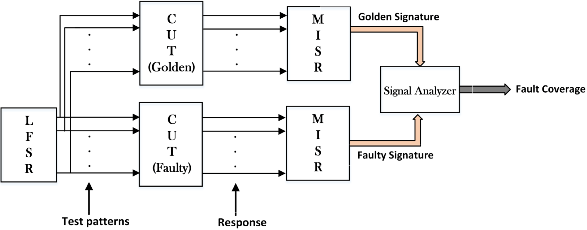
A4. Our offline version of a Built In-Self Test architecture contains a Test Pattern Generator (TPG) that has the role to stimulate the Circuits Under Test with test vectors that are injected in the chain. These test vectors are processed by the circuits according to their internal logic and are generated as responses at their outputs. From here the responses are collected by an Output Response Analyzer (ORA) which generates a final signature for each of the circuits in the chain via EXOR gate operations. Therefore we can detect a single bit as well as single stuck-at faults using the manually configured LFSR with the help of the primitive polynomial function that can generate 65.536 distinct test patterns.
Q5. Are the components from your previous answer the only elements that you used for constructing the OBIST architecture?
A5. Additionally, we used Analog to Digital Converters (ADCs) as well as their counterparts (DACs) to translate signals to purely binary or analog values for them to being processed correctly by our testing architecture. A classical example of an ADC is the LM741 amplifier equipped with multiple resistors at the input that can generate a logical level (either 1 or 0) depending on its input voltages. Since our final testing solution is an online version of a BIST architecture we used an Idle State Detector to determine if the solar tracking system is active or not.
Q6. How does the final assembled architecture look like then?
A6. As mentioned previously depending on the input sensor values of the Solar Tracking device the Idle State Detector will calculate a binary value based on the combination of XOR and OR gates to establish if the system is idle or not. A more concrete example here would be: if for instance, we have the following voltage readings 0.56, 0.59, 1.23, and 1.25, these values will be trimmed to their nearest binary value (0 or 1). By injecting these Boolean values in the combinational circuit of the Idle State detector we will obtain only one binary number which tells us if the solar panel is moving or not. If the solar panel is still moving, Switches Batches A will be set on 1 and Switches Batches B on 0 and if it is idle vice-versa.
Q7. How does the Software Implementation distinguish itself from the hardware configuration?
A7. Our Software implementation follows a similar pattern to the Fault Injection Strategy in the way the analog values and functions of the Circuits Under Test were encoded in binary format. For instance, the analog values of the Optocoupler smaller or equivalent to 0.6 were denoted with don’t care elements while the analog value 4.5 was treated in the same manner. For the motor drivers further shifting of the digital values was authorized by an Enable line and the Multiple Input Shift Register was declared as an XOR operation between an input and an output.
Q8. Was the OBIST solution efficient in detecting hardware faults?
A8. For the experimental setup, we implemented a Test Mode Architecture which employs a single LFSR, two Circuits under Test (a golden and a faulty one), and two distinct MISR devices to feed the Signal Analyzer with faulty and healthy signatures. Ultimately, the Signature Analyzer will compare the faulty signatures with the golden ones and will establish the fault coverage. Overall, we obtained an average 93, 90 % fault coverage for random single bit flips in the 8 least significant positions of the test chain while for single stuck-at faults the coverage was rated at 100 % for the same bit range. The Global Fault Coverage for 12 random bits was rated at 96.96 %. In our case, aliasing occurs in very rare cases and can be calculated by using a mathematical formula.
Q9. What were the conclusions fo your paper and is there any future work in progress?
A9. We proposed an OBIST architecture that uses an LFSR as a TPG and a MISR as a result gatherer for testing our solar tracking equipment composed of an Optocoupler, an Arduino UNO and two L298N Dual-H Bridges Ics. Due to the proposed fault injection strategy, we concluded that all 4 CUTs are prone to hardware faults and thus we implemented software as well as hardware solutions for the proposed OBIST. We obtained 93.93% coverage for single bit-flip errors (last 8 bits, mutant) and 100% coverage for single stuck-at-faults (for 8, 12, and 16 random bits). Finally, the proposed OBIST achieves a total global coverage of 96.96% for the targeted errors, resulting in an efficient architecture regarding coverage and cost points of view. As future work, we propose to extend the range of hardware faults from a single bit to double bit, and why not even multiple bit errors in a single row.
Q10. What is the main advantage of OBIST architecture?
A10. From our point of view, the main advantage of OBIST architecture is the possibility of simulating hardware faults in a software environment. This does not only reduces the costs of additional test equipment but can also bring the benefit of not damaging the circuits under test.

Neueste Kommentare