Ich habe hier vor einigen Monaten über unseren Erfolg beim Bau eines sensorlosen, erschwinglichen Flying-Probe-inspirierten In-Circuit-Testers für die Leiterplatten-Evaluierung mit Anwendung in der Testingenieurausbildung geschrieben.
Wir werden morgen das Forschungspapier über dieses Testgerät auf der internationalen IEEE-Konferenz 2020 über Umwelt und Elektrotechnik in Madrid, Spanien, vorstellen unter „EDUCATION IN ELECTRICAL ENGINEERING“.
 Zusammenfassung: In diesem Beitrag wird ein hybrides sensorloses In-Circuit-Tester (ICT) Design vorgestellt, das die Eigenschaften des Flying-Probe-Tests (FPT) und die Fähigkeiten einer Koordinatenmessmaschine (CMM) kombiniert. Die experimentellen Ergebnisse zeigen, dass der vorgeschlagene Flying-Probe-inspirierte ICT (FPICT) für kleinere Leiterplatten geeignet ist und sich als effizient hinsichtlich der Präzision (Gesamtpräzision von 95,70% für den Messtest), der Testzeit (durchschnittlich 10,35s für einen Ein-Punkt-Testzyklus), des Stromverbrauchs (insgesamt 3,92 Watt für alle betrachteten Testfälle) und der Kosten (etwa 25 Dollar) erweist, wobei er im Vergleich zu den traditionellen und teuren FPTs, die in der Industrie zu finden sind, viel erschwinglicher und benutzerfreundlicher ist.
 Sie können den Artikel hier lesen.
Hier habe ich alle Projektdateien bezüglich unserer erschwinglichen Flying-Probe-inspirierten In-Circuit-Testers für die Leiterplatten-Evaluierung mit Anwendung in der Testingenieurausbildung veröffentlicht.
CONSTRUCTIVE ELEMENTS OF THE DEVICE EQUIPPED WITH MOBILE PROBE
- Electronic assembly
- a) 1 x Arduino Mega 2560 Microcontroller
- b) 3 x ULN2003A Motor Drivers
- c) 3 x 28BYJ-48 Unipolar Stepper Motors
- d) 3 x 3D Printer Mechanical Endstop Limit Switch
- e) 1 x Golden Pogopin (telescopic golden pin)
- The mechanical structure
2.1. X-axis component
- a) 4 x Plastic guide rails ( h = 25 mm, l = 20 mm,
g = 10 mm ), h – height, l – width, g – thickness
- b) 2 x Metal bars ( L = 180 mm), L – length
- c) 1 x U-shaped aluminum sheet conveyor ( L =
120 mm, l = 105 mm ), U = 25 mm
- d) 1 x Rack ( L = 130 mm), L – length
- e) 2 x Metal rod sliding brackets ( g = 10 mm, L =
85 mm ), g – thickness, L – length
2.2. Y-axis component
- a) 1 x U-shaped aluminum sheet conveyor ( L =
70 mm, l = 50 mm), U = 20 mm
- b) 1 x U-shaped aluminum sheet platform ( L
= 220 mm, l = 50 mm), U = 10 mm
2.3. Z axis component
- a) Cam mechanism (oval disc with different diameters)
eccentricity – 5 mm
- b) Hexagonal bar ( L = 80 mm), L – length
- c) Counterweight disc ( D = 27 mm), D – diameter
- Additional parts
❖ Working table (parquet board L = 430 mm , l = 200 mm )
❖ Screws ( L = 5 mm, 10 mm )
❖ Threads
❖ Nuts
❖ Support scale for 1 x MELS
❖ 2 x Ladder (unit step) for the Stepper engine
❖ 4 x Test plate mounting screws (insulated)
Affordable Flying Probe-Inspired In-Circuit-Tester for Printed Circuit Boards Evaluation with Application in Test Engineering -ArduinoMega2560 Code.ino
/*
* Author: Sorin Liviu Jurj
* This code is part of a paper called „Affordable Flying Probe-Inspired In-Circuit-Tester for Printed Circuit Boards Evaluation with Application in Test Engineering Education“. More information about the paper you can find here: https://jurj.de/affordable-flying-probe-inspired-in-circuit-tester-for-printed-circuit-boards-evaluation-with-application-in-test-engineering-education
*
*/
#include <Stepper.h>
#define STEPS_PER_REVOLUTION 2048 //steps takes for the stepper motor for one complete revolution (refer stepper motor manual/doc)
#define MOTOR_SPEED1 15 //speed of motor X
#define MOTOR_SPEED2 15 //speed of motor Y
#define MOTOR_SPEED3 13 //speed of motor Z
#define MM_PER_STEP 0.10 //mm the arm moves for one step of stepper (do trial and run testing for finding this value) initial 7
#define TOTAL_VOLTAGE_PARAMS 5 //total number of voltage parameters to be tested
#define TOTAL_CURRENT_PARAMS 0 //total number of current parameters to be tested
#define RES_CUR_MEASURE 100 //Resistance in ohms between test points for Current measurement
#define STEPS_PER_MM 100 // This is an average value, not completely accurate
/*ENUM to configure stepper directiobn*/
typedef enum{
STEPPER_MOVE_FORWARD,
STEPPER_MOVE_BACKWARD,
}Stepper_Dir_t;
/*
configuration structure declaration for checking voltage
*/
typedef const struct {
int Dist_X_mm; //X distance in mm from reference point to test point
int Dist_Y_mm; //Y distance in mm from reference point to test point
int Dist_Z_mm; //Z distance in mm from reference point to test point
float volExpectedL; //expected voltage lower value in volts
float volExpectedH; //expected voltage higher value in volts
char param[25]; //parameter description
}configStruct_vol;
/*
configuration structure final with exact steps and counts from mm and voltage value
*/
typedef struct {
int Dist_X_step; //no of steps for motor to reach test point from reference point – X
int Dist_Y_step; //no of steps for motor to reach test point from reference point – Y
int Dist_Z_step; //no of steps for motor to reach test point from reference point – Z
int CountExpectedL; //expected voltage lower value in count
int CountExpectedH; //expected voltage higher value in count
}configFinalStructVol_t;
/*
configuration structure declaration for checking current
*/
typedef const struct {
int Dist_X1_mm; //X distance in mm from reference point to first test point
int Dist_Y1_mm; //Y distance in mm from reference point to first test point
int Dist_X2_mm; //X distance in mm from reference point to second test point
int Dist_Y2_mm; //Y distance in mm from reference point to second test point
int Dist_Z_mm; //Z distance in mm from reference point to test point
int curExpectedL; //expected current lower value in milliamps
int curExpectedH; //expected current higher value in milliamps
char param[25]; //parameter description
}configStruct_cur;
/*
configuration structure final with exact steps and counts from mm and current value
*/
typedef struct {
int Dist_X1_step; //no of steps for motor to reach first test point from reference point – X
int Dist_Y1_step; //no of steps for motor to reach first test point from reference point – Y
int Dist_X2_step; //no of steps for motor to reach second test point from reference point – X
int Dist_Y2_step; //no of steps for motor to reach second test point from reference point – Y
int Dist_Z_step; //no of steps for motor to reach test point from reference point – Z
}configFinalStructCur_t;
/*
configuration structure for each params for voltage measurement
User should configure this structure
*/
configStruct_vol myConfigStruct_vol[TOTAL_VOLTAGE_PARAMS] = {
{16.98,11.95,15,4.5,5.0,“param1″}, //Pinul 7 – cu o valoare standard de 5V – Atmega328
{19.99,8.0,15,4.5,5.0,“param2″}, //Pinul 20 – cu o valoare standard de 5V – Atmega328
{19.96,8.0,15,4.5,5.0,“param3″}, //Pinul 21 – cu o valoare standard de 5V – Atmega328
{36.90,17.95,15,4.5,5.0,“param4″}, //Pinul 31 – cu o valoare standard de 5V – Atmega16u2
{38.02,18.60,15,4.5,5.0,“param5″}, //Pinul 32 – cu o valoare standard de 5V – Atmega16u2
};
/*
configuration structure for each params for current measurement
User should configure this structure
SW should check voltage on test point 1 and 2 and find the drop across the resister(user configured) between these two points
to find the current through the path
*/
configStruct_cur myConfigStruct_cur[TOTAL_CURRENT_PARAMS] = {
//{20,20,30,20,20,30,23,“param6″}, // ex: test point1 – (50,60,40) , test point2 – (30,10,40) , expected current range 15-23 mA
//{20,20,30,20,20,30,25,“param7″},
//{20,20,30,25,20,30,25,“param8″},
//{20,20,30,25,20,30,25,“param9″},
};
configFinalStructVol_t configFinalStructVol[TOTAL_VOLTAGE_PARAMS]; //structure for storing test point info (steps and count) for voltage
configFinalStructCur_t configFinalStructCur[TOTAL_CURRENT_PARAMS]; //structure for storing test point info in steps for current
/*stepper motors initialised
IO pins used for stepper motors
X – 22,23,24,25
Y – 26,27,28,29
Z – 30,31,32,33
*/
Stepper stepperX(STEPS_PER_REVOLUTION, 22, 23, 24, 25);
Stepper stepperY(STEPS_PER_REVOLUTION, 26, 27, 28, 29);
Stepper stepperZ(STEPS_PER_REVOLUTION, 30, 31, 32, 33);
int i;
/*
* End point object
*/
class endpoint_t{
uint8_t pin;
Stepper* stepper;
public:
endpoint_t(int p, Stepper* mystepper): pin(p), stepper(mystepper) {} ;
void to_endpoint(void){
//Serial.println(„Starting endpoint localization …“);
while(digitalRead(pin)){ // move until we have reached the endpoint
stepper->step(-100);
}
//Serial.println(„Localization complete …“);
}
};
#define x_endpoint 46 // pin definitions
#define y_endpoint 47
#define z_endpoint 48
endpoint_t* x_axis_endpoint; // define endpoints
endpoint_t* y_axis_endpoint;
endpoint_t* z_axis_endpoint;
void setup() {
//Initialise serial
Serial.begin(9600);
while(!Serial);
// set speed of stepper motors
stepperX.setSpeed(MOTOR_SPEED1);
stepperY.setSpeed(MOTOR_SPEED2);
stepperZ.setSpeed(MOTOR_SPEED3);
x_axis_endpoint = new endpoint_t(x_endpoint, &stepperX);
y_axis_endpoint = new endpoint_t(y_endpoint, &stepperY);
z_axis_endpoint = new endpoint_t(z_endpoint, &stepperZ);
toReferencePoint();
/*
convert arm movement distance to steps and voltage to count
*/
Serial.println(„Converting distances to steps: „);
for (i = 0; i < TOTAL_VOLTAGE_PARAMS ; i ++){
configFinalStructVol[i].Dist_X_step = (myConfigStruct_vol[i].Dist_X_mm) * STEPS_PER_MM;
configFinalStructVol[i].Dist_Y_step = (myConfigStruct_vol[i].Dist_Y_mm) * STEPS_PER_MM;
configFinalStructVol[i].Dist_Z_step = (myConfigStruct_vol[i].Dist_Z_mm) * STEPS_PER_MM;
configFinalStructVol[i].CountExpectedL = (1023 * (myConfigStruct_vol[i].volExpectedL)) / 5;
configFinalStructVol[i].CountExpectedH = (1023 * (myConfigStruct_vol[i].volExpectedH)) / 5;
}
/*
convert arm movement distance to steps for tesing current at testing points
*/
for (i = 0; i < TOTAL_CURRENT_PARAMS ; i ++){
configFinalStructCur[i].Dist_X1_step = (myConfigStruct_cur[i].Dist_X1_mm) * STEPS_PER_MM;
configFinalStructCur[i].Dist_Y1_step = (myConfigStruct_cur[i].Dist_Y1_mm) * STEPS_PER_MM;
configFinalStructCur[i].Dist_X2_step = (myConfigStruct_cur[i].Dist_X2_mm) * STEPS_PER_MM;
configFinalStructCur[i].Dist_Y2_step = (myConfigStruct_cur[i].Dist_Y2_mm) * STEPS_PER_MM;
configFinalStructCur[i].Dist_Z_step = (myConfigStruct_cur[i].Dist_Z_mm) * STEPS_PER_MM;
}
Serial.println(„Setup complete.“);
}
String str ;
String startstr = String(„START“) ;
int count ;
float voltage1,voltage2;
int cur_mA;
void loop() {
/*check if user inputs via serial*/
if(Serial.available()>0){
str = Serial.readString();
/*check if user inputs START via serial*/
if(str.equals(startstr))
{
Serial.println(„STARTING UP….“);
for (i = 0; i < TOTAL_VOLTAGE_PARAMS ; i ++){
Serial.print(myConfigStruct_vol[i].param);
/*locate the arm to pogo pin position from reference point*/
stepperMove(
configFinalStructVol[i].Dist_X_step,
configFinalStructVol[i].Dist_Y_step,
configFinalStructVol[i].Dist_Z_step,
STEPPER_MOVE_FORWARD,
STEPPER_MOVE_FORWARD,
STEPPER_MOVE_FORWARD
);
delay(500);
/*read the analog value from the test point*/
count = analogRead(A0);
delay(1000); // delay before we start retracting probe
/*retract arm to reference point*/
toReferencePoint();
delay(50);
/*checks if the voltage is beyond expected range*/
if((count < configFinalStructVol[i].CountExpectedL) || (count > configFinalStructVol[i].CountExpectedH)){
Serial.println(“ : FAILED“);
//continue;
}
else{
Serial.println(“ : SUCCESS“);
}
Serial.println(„finished parameter: “ + String(i));
}
/*
check if voltage values tested successfully at test points
*/
if(i == TOTAL_VOLTAGE_PARAMS){
/*Current values testing on the test points*/
for (i = 0; i < TOTAL_CURRENT_PARAMS ; i ++){
Serial.print(myConfigStruct_cur[i].param);
/*locate the arm to test point 1 from reference point*/
stepperMove(configFinalStructCur[i].Dist_X1_step,configFinalStructCur[i].Dist_Y1_step,configFinalStructCur[i].Dist_Z_step,STEPPER_MOVE_FORWARD);
delay(10);
/*read the voltage value from the test point*/
voltage1 = (float)(analogRead(A0) * 5) / 1023;
/*retract arm to reference point*/
stepperMove(configFinalStructCur[i].Dist_X1_step,configFinalStructCur[i].Dist_Y1_step,configFinalStructCur[i].Dist_Z_step,STEPPER_MOVE_BACKWARD);
delay(10);
/*locate the arm to test point 2 from reference point*/
stepperMove(configFinalStructCur[i].Dist_X2_step,configFinalStructCur[i].Dist_Y2_step,configFinalStructCur[i].Dist_Z_step,STEPPER_MOVE_FORWARD);
delay(10);
/*read the voltage value from the test point*/
voltage2 = (float)(analogRead(A0) * 5) / 1023;
/*retract arm to reference point*/
stepperMove(configFinalStructCur[i].Dist_X2_step,configFinalStructCur[i].Dist_Y2_step,configFinalStructCur[i].Dist_Z_step,STEPPER_MOVE_BACKWARD);
delay(10);
/*Find current across the resistor*/
cur_mA = ((voltage2 – voltage1)/RES_CUR_MEASURE) * 1000 ;
/*checks if the current is beyond expected range*/
if((cur_mA < myConfigStruct_cur[i].curExpectedL) || (cur_mA > myConfigStruct_cur[i].curExpectedH)){
Serial.println(“ : FAILED“);
break;
}
else{
Serial.println(“ : SUCCESS“);
}
}
/*
check if voltage values tested successfully at test points
*/
if(i == TOTAL_CURRENT_PARAMS){
Serial.println(„FINAL TEST STATUS : SUCCESS“);
}
/*
ERROR in tesing current values
*/
else{
Serial.println(„FINAL TEST STATUS : FAILED“);
Serial.println(„ENTER START TO INITIALIZE.. „);
}
}
/*
ERROR in tesing voltage values
*/
else{
Serial.println(„FINAL TEST STATUS : FAILED“);
Serial.println(„ENTER START TO INITIALIZE.. „);
}
}else{
Serial.println(„INVALID COMMAND.. „);
}
}
}
/*
Funtion to Move stepper forward and backward
*/
void stepperMove(int x,int y, int z , Stepper_Dir_t xdir, Stepper_Dir_t ydir, Stepper_Dir_t zdir){
if(xdir == STEPPER_MOVE_FORWARD){
stepperX.step(x);
}else{
stepperX.step(-x);
}
if(ydir == STEPPER_MOVE_FORWARD){
stepperY.step(y);
}else{
stepperY.step(-y);
}
delay(2000);
if(zdir == STEPPER_MOVE_FORWARD){
stepperZ.step(z);
}else{
stepperZ.step(-z);
}
}
void stepperMove(int x,int y, int z , Stepper_Dir_t dir){
switch (dir){
case STEPPER_MOVE_FORWARD:
stepperX.step(x);
stepperY.step(y);
stepperZ.step(z);
break;
case STEPPER_MOVE_BACKWARD:
stepperZ.step(-z);
stepperY.step(-y);
stepperX.step(-x);
break;
default:
break;
}
}
/*
* Function that returns probe to reference point
*/
void toReferencePoint(){
z_axis_endpoint->to_endpoint();
x_axis_endpoint->to_endpoint();
y_axis_endpoint->to_endpoint();
}
Questions Regarding the “Affordable Flying Probe-Inspired In-Circuit-Tester for Printed Circuit Boards Evaluation with Application in Test Engineering Education” Article
Q1. What was the motivation behind the implementation of an affordable flying probe testing device that can be used to check Printed Circuit Boards interconnects?
A1. We consider that PCB testing is a very important stage of the manufacturing process of Integrated Circuits in the industrial environment. However, from an educational point of view, the large number of technical books does only offer theoretical information to students without allowing them to have practical experience with real parameter values of a PCB. Additionally, we are aware that laboratories are not properly equipped with testing facilities since industrial Flying probers are usually very expensive. Therefore we propose a portable, low-cost, and sensorless In-Circuit-Tester that can be easily integrated into schools and universities.
Q2. What are the hardware components that you used to construct the Flying Probe Tester?
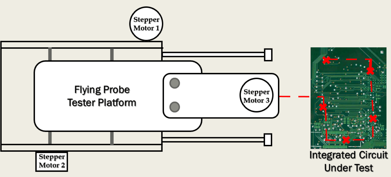
A2. Our proposed Flying Probe Inspired In-Circuit Tester is composed of mechanical components, as well as electrical components. In this answer, however, I will place a much greater highlight on the mechanical components. Generally speaking, a Flying Probe Tester is a testing device that operates in a tridimensional space and consequently, our prototype is constructed around three main axes.
The first one is the X-Axis which is placed at the inferior part of the main platform and moves according to the interaction between the Stepper motor’s smaller cogwheel and a 130 mm long rack. The reference point of the X-axis is established by a static deployed Mechanical End Stop Limit Switch.
The Y-Axis is located on top of the main platform and is composed of two metal rods, one of them being a long screw which interacts with the Stepper motor on the other end. Since the Stepper motor rotates the screw in two distinct directions, the secondary platform will be translated according to the straight drill rule, acting like a nut on the screw. The Mechanical End Stop Limit Switch is translated together with the Y-Axis system and establishes the reference point when the switch interacts with one of the walls of the main platform.
The Z-Axis was the most complex to build of the three-axis and is mounted on the previously mentioned secondary platform, while the working principle is identical to the Y-Axis. The probe consists of a pogo pin which is located at the end of a 60 mm hexagonal nut and can interact with the contacts of the desired Circuit under Test (in our case the Arduino UNO board).
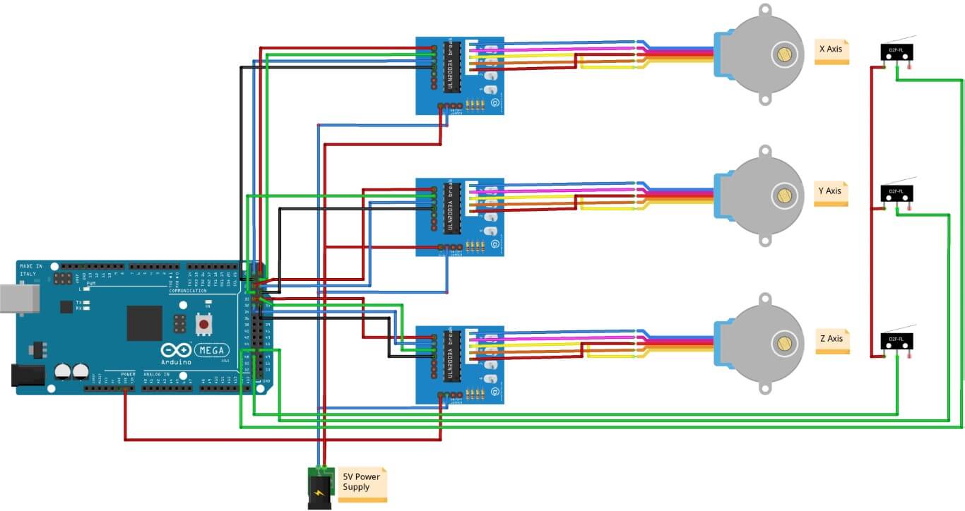
Q3. What are the electrical components that you used to construct the Flying Probe Tester?
A3. All three mechanical axis described earlier are controlled by electrical equipment composed of an Arduino MEGA2560 microcontroller, 3 ULN2003A motor drivers, 3 28BYJ-48 steppers, and their Mechanical End-Stop Limit Switches (MELS). The three Mechanical End stop Limit Switches are also connected to the Arduino Mega board to determine the starting point of the three-axis. Although our device can be directly powered by a laptop or tablet we recommend using an external 5V power supply so that the stepper motors can operate at their full potential.
Q4. How does the Sensorless based Test Point Tracking influence the performance of your device?
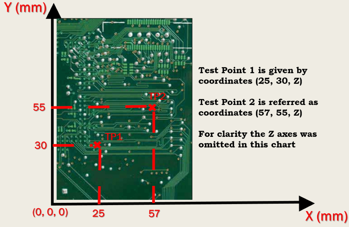
A4. Our Sensorless – Based Test Point Tracking eliminates the requirement of expensive optical sensors which are usually equipped on each of the three mechanical axes and reduces the cost of our device by employing a very straightforward working principle. The distance in steps from the reference point is calculated by multiplying the Cartesian coordinate in millimeters by the value in millimeters of a single step executed by the motor engine. With the converted distances in steps and other additional variables, we can test either voltage or current parameters or even both, while the test program will generate a final report with all the checked values from the targeted pins.
Q5. Your article also addresses the problem of Configurable Data Files and Structures. Can you further detail these concepts?
A5. The proposed Configuration File Structures are flexible enough to be manipulated by any student, being very easy to learn and understand. One example of such a configuration file is given by the order of the variables (Dist_X, Dist_Y, Dist_Z, LowVoltage, HighVoltage, and Parameter Number) which is very important for the test program to run in optimal condition. Besides the Cartesian coordinates which have to be measured by the user manually, we can also distinguish the parameter values with the lower and higher values being extracted from a specialized catalog. If the checked value falls between the valid ranges the tested pin is working properly otherwise there might be a certain failure of an area of the Circuit under Test.
Q6. How did you demonstrate the efficiency of your Flying Probe Tester prototype?
A6. We proved the efficiency of our device by employing a test platform. For the final experimental setup, we used a digital caliper to obtain the Cartesian coordinates for all targeted test points. For a total number of 500 cases dedicated to single-point testing, we obtained 100 % precision with an average time of 10.35 seconds. For the Multiple Point Testing with the same number of test samples, we obtained 91.40 % precision coverage with an average time of 62.69 (multiple point testing usually involves several test pins across the board and therefore takes more time to execute, not to forget the fact that current parameters require two test points instead of only one such as in the case of voltage testing). Overall, for measurement testing, we obtained 95.70 precision coverage and very low execution time (1 second and a half which takes for the probe to collect the parameter value of the test pin). The power consumption of the device was evaluated somewhere around 3.8 Watts inactive state and not exceeding more than 4 Watts when operating. In the idle state, the power consumption was always rated under 0, 5 Watts.
Q7. We observed that you provided a demonstration video of your Flying probe Inspired in Circuit Tester. Can you tell us exactly what we can see in the below 1-minute video sample?
A7. We recorded a video of our initial FPICT prototype to convince people that the combination between Flying Probe Testers and Coordinate Measuring Machines is a feasible solution. In the provided video you can see an initial glimpse of the User Interface (which in our case is the Arduino UNO IDE Suite) with all the coordinates and parameter values inserted by the user manually. The video then skips to the moment where the flying probe is engaged with single-point testing. Single Point Testing refers to the fact that the testing device is programmed to collect parameter readings from only one test node and tests are repeated to check the placement precision of the pogo pin. The process itself is not simple because all coordinates must be calculated, including the Z-axis (which controls the pogo pin) to avoid too much pressure or damage to the board’s pins. In the final part of the video, you can see a sample of a generated report which refers to only one test routine. It is a fact that several test routines must be executed by the FPICT device to validate its efficiency.
Q8. Can you name a few advantages of your proposed FPICT device?
A8. In the conclusions section of our work, we listed several advantages of the Flying probe device:
• Very easy to learn and use, especially because of the C written configuration files (e.g. which can be easily modified by the students in a laboratory)
• It has a friendly user interface and can be also quickly connected to any existent computing platform that has a USB port (Desktop PCs, laptops, tablets)
• While measurements by a technician can replace the operations of our device, we find that the automation method is more convenient and saves time for checking a large volume of PCBs, compared to manual measurements made with the standard measuring device that needs to be repeated for each PCB
• Provides students easy access to study and experiment with the inner workings of an FPT when operating on a real PCB board, which otherwise would have been almost impossible, given the fact that the FPT’s found in the industry are very expensive (i.e. thousands of dollars compared to our FPICT which costs around 25 dollars and require no extra costly licenses).
• Students will find learning and practicing the testing of PCBs to be more fun and interesting experience
Q9. Can you list a few disadvantages of your proposed FPICT device?
A9. We are aware of the fact that no project is perfect and consequently our work suffers in the following areas:
• Due to the low-cost components, mechanical imperfections are hindering our device from achieving a better score in Multiple Point Testing.
• Our FPICT returns after each measurement to its reference point, which is a time-consuming process.
• In comparison with other Flying Probe devices found in the industry, our In-Circuit Tester can evaluate only small-sized PCBs.
• Test coverage can be determined by a limited number of test nodes because our FPICT can measure only voltage and current parameters. This aspect is also enforced by the idea that not all test nodes are accessible due to the manufacturing process or small size access pins that can be hardly reached by the test probe.
Q10. What do you plan to realize as a future work?
A10. As mentioned before our proposed In-Circuit Tester lacks some of the qualities of a professional Flying probe device and this allows room for further improvements. For instance, in order to reduce test time, the main algorithm can be changed so that the flying probe memorizes its current position instead of going back to its initial starting point each time a coordinate has been reached. Additionally, the mechanical template can be restructured by extending its size to test medium-sized PCBs and why not, even entire motherboards. Another future perspective is to implement a Deep-Learning-based system that can assist our FPICT in identifying areas that are worth testing. In other words, a Deep-Learning-based mapping procedure might examine the entire board before testing in order to detect regions of the PCB that could present defects such as shortcircuits or open circuits. This does not only reduce testing time drastically but also brings a more AI-oriented approach to the main problem. Nevertheless, our next step is to mass-produce the proposed FPT and deliver it to as many engineering laboratories in the country (and beyond) as possible.

Neueste Kommentare